

 Online Consultation
 Product Manual
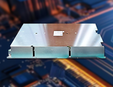
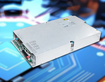
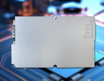
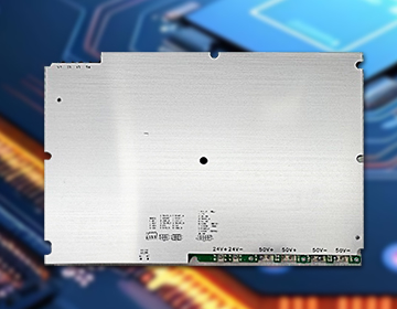
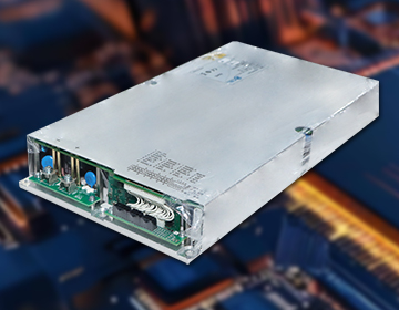
20kW (GD231)
This rectifier module features a three-phase AC input voltage range of 187–480Vac, delivering a main output of 10–250Vdc and an auxiliary output of 24Vdc with active power factor correction. It incorporates input overvoltage/undervoltage protection, phase loss protection, output overload protection, output overvoltage protection, output short-circuit protection, overtemperature protection, and RS485 communication capabilities.